How To Create An Isolated Ground
The Isolated Ground

By: | May 09, 2019
The Isolated Ground (IG) is a type of equipment ground that, in theory, reduces interference experienced by electronics and instrumentation from radio frequency (RF) noise, by connecting that equipment directly to the grounding terminal of the service equipment, without ever making contact with another metal component or grounded surface, that could potentially be serving as an antenna for airborne RF noise.
Isolated Ground System
TheIsolated Ground system (IG), relies on bringing an Equipment Grounding Conductor (EGC), all the way from the point of ground-origin, (such as a load center / electrical panel / etc.) to the point where it terminates onto the load that it is serving – without ever contacting another equipment ground, metal outlet box, metallic conduit system, etc. This method of specialized grounding has been a widely-accepted practice, for the minimizing of Radio-Frequency (RF) feedback(s) on computer and electronic branch-circuit equipment grounds, for decades.
When the required Equipment Grounding Conductor (EGC) within a branch-circuit is connected to delicate instrumentation or sensitive electronics, reducing or eliminating the "antenna effect" of that conductor, and its ability to pick up various airborne radio frequency, is tops on everyone's "to-do" list when it comes to protecting that sensitive equipment from damage, as well as establishing a dependable baseline for dialing-in the equipment for consistent readings and results. RF interference is the enemy of "consistency" when you are dealing with low output/input equipment.
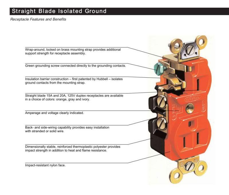
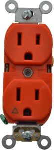
The Isolated Ground system, generally serves its intended load or device in the form of an Isolated Grounding Receptacle, connected to the aforementioned "Isolated" Equipment Grounding Conductor (EGC). This conductor is shielded from excessive RF noise by donning a mandatory insulation along its entire length. Again, this Isolated Grounding Conductor is required to stay remote (disconnected) from all other grounding splices within the grounding system, until it reaches its target:the EGC terminal bar inside of the panel.
The purpose: To keep unwanted RF noise from entering our delicate electronics via the EGC.
By insulating the Isolated Grounding conductor for its entire length, and then prohibiting additional splicing on this conductor to boot, we are providing the equipment grounding conductor a path back to the electrical panel, without allowing it to ever touch another piece of conductive metal on its way there; a "conductive metal" thatmay be serving as an antenna for RF noise, through its deliberate contact with structural, plumbing, and electrical system metal throughout the building.
Utilizing an Isolated Grounding system is a well-known and widely accepted method for reducing this interfering (if not damaging) "noise" on electronics, when RF is abundantly present. However, there are some that speculate as to whether the practice of installing an Isolated Ground works- at all! And stand in firm opposition to those who would recommend it as a solution, citing that it can actually INCREASE RF interference, instead of reducing it.
Regardless of which camp you fall in, "for" or "against" ….the Isolated Ground can also serve one other purpose . It can function as the equipment grounding conductor (EGC) for a device or load, while providing protection for that load, from any "objectionable current" that may be occurring on the grounding system of that electrical system.
Objectionable Current is not the same as RF Noise.
Objectionable current is a measurable current that flows on the EGC system, that ought not be there, butisthere due to some improper connection between a grounded conductor (aka white conductor) and a grounded metal surface, or grounding conductor, somewhere else within the system. Objectionable current can also be present because of a failure in a connected-load somewhere, that is letting current bleed through an insulating material and on to the ground of that load, and as a consequence- on to the groundingsystem of the entire electrical system.
This minimal amount of objectionable current that can sometimes be found on the grounding systems of large and/or older electrical systems, is typically of no consequence to normal inductive/resistive loads, and simply put, doesn't hurt anything. But for delicate Solid-State electronics, this minimal current on the equipment ground, can wreak electrical havoc.
By using an Isolated grounding conductor, andthen that conductor(by default) not touching any portion of the potentially "charged" equipment grounding system, you have greatly reduced the possibility of that minute electrical charge on the grounding system, being redirected "upwards" through your load's EGC and into your delicate load's electronics. And instead, you have moved the point at which your load's EGC makes contact with this slightly charged equipment grounding system, so that it will be so far away from your delicate equipment, and so close to where the main bonding jumper (MBJ) ties the grounding system, in with the grounded (neutral) of the system, that the objectionable current will have no choice at all, butthe choiceof "least resistance," whereby the current must leave the premises wiring – as well as your delicate electrical load – altogether, and exit the premises by way of the service neutral, all the way to the grounded utility co. transformer.
Why does this matter?
It is a fair question, regarding objectionable current that may be present on a grounding conductor, to ask why one should be concerned with it at all, since the EGC that would contain this minimal current would find nothing in the form of a complete circuit in which to "flow" on the grounded metal parts of your equipment. In other words, the equipment grounding conductor in your equipment cord is attached to the metal casing of your equipment, and then stops there. There is no complete path to allow current flow, therefore there should be no magnetic field near my equipment.
I offer this as a reasonable response: The computer tower beneath my writing desk is assembled with a metal enclosure. The 3-wire cord from that computer tower has the grounding wire contained in the cord, and it is soldered/clipped to the inside of the metal casing of my computer tower. The other end of the ground in that cord is attached to the grounding prong on the male plug-end of the cord, and then in contact with the grounding system of my office wiring, by way of my 3-prong grounding receptacle in the wall. If I place this metal cased computer against copper plumbing pipe coming out of the floor, or a steel column coming from the floor, a metal desk in contact with the concrete slab floor, or ANYTHING grounded, and there is objectionable current on the grounding system of my office electrical system, then there will be a constant magnetic field being induced around my entire computer processer, as current flows from the equipment ground of my computer circuit, to the grounded component my computer is touching.
And with that, I yield the floor to the Isolated Grounding Receptacle-

How To Create An Isolated Ground
Source: https://www.jadelearning.com/blog/the-isolated-ground/
Posted by: aldrichfater1942.blogspot.com

0 Response to "How To Create An Isolated Ground"
Post a Comment